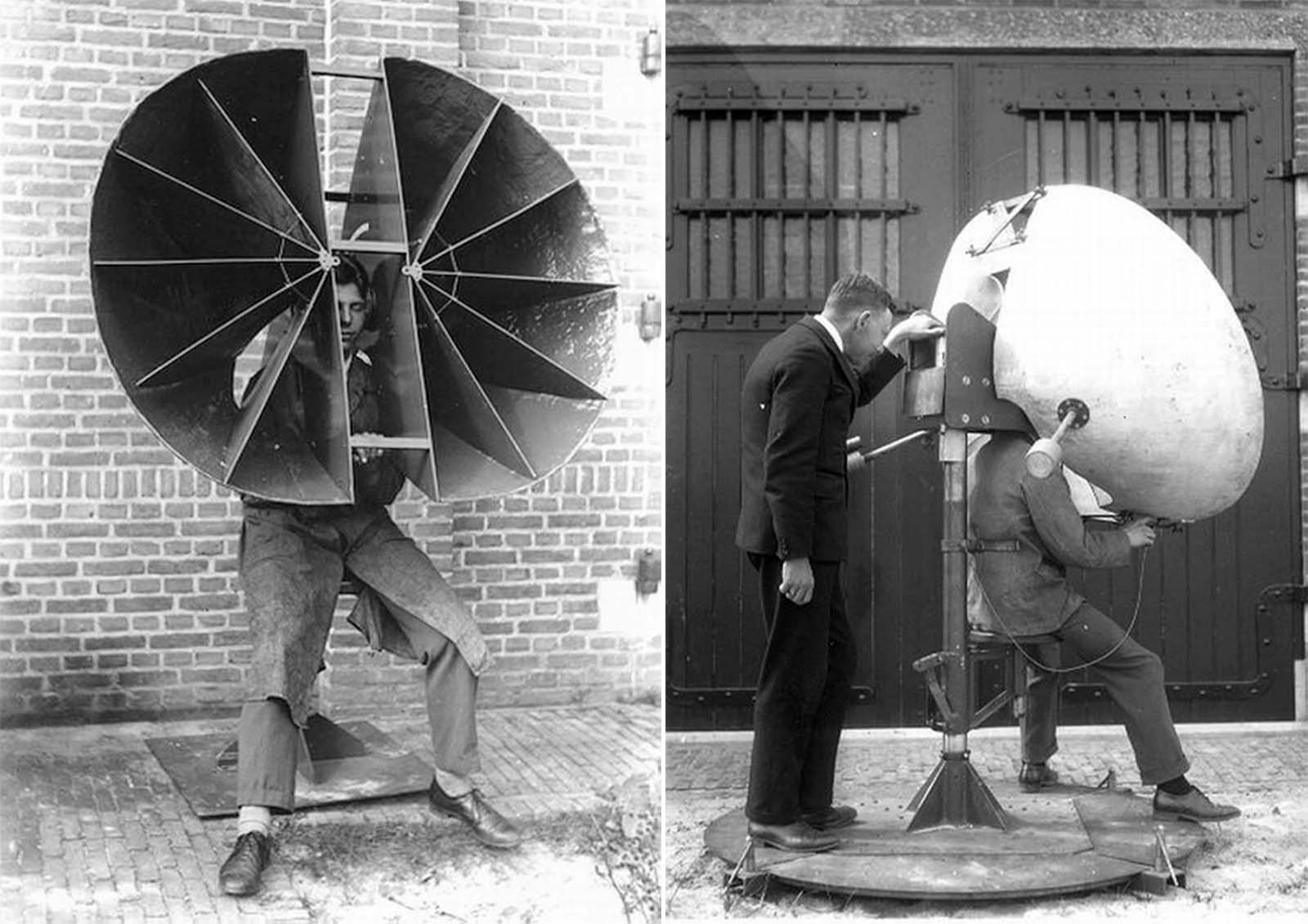
Aircraft engines produced unprecedented sound, so in order to hear them at a distance, the war efforts developed listening devices. A two-horn system at Bolling Field, USA, 1921.
Acoustic location was used from mid-WW1 to the early years of WW2 for the passive detection of aircraft by picking up the noise of the engines.
Passive acoustic location involves the detection of sound or vibration created by the object being detected, which is then analyzed to determine the location of the object in question.
Horns give both acoustic gain and directionality; the increased inter-horn spacing compared with human ears increases the observer’s ability to localize the direction of a sound.
Acoustic techniques had the advantage that they could ‘see’ around corners and over hills, due to sound refraction. The technology was rendered obsolete before and during WW2 by the introduction of radar, which was far more effective.
The first use of this type of equipment was claimed by Commander Alfred Rawlinson of the Royal Naval Volunteer Reserve, who in the autumn of 1916 was commanding a mobile anti-aircraft battery on the east coast of England.
He needed a means of locating Zeppelins during cloudy conditions and improvised an apparatus from a pair of gramophone horns mounted on a rotating pole.
Several of these pieces of equipment was able to give a fairly accurate fix on the approaching airships, allowing the guns to be directed at them despite being out of sight.
Although no hits were obtained by this method, Rawlinson claimed to have forced a Zeppelin to jettison its bombs on one occasion.

German sound location, 1917. The photograph shows a junior officer and a soldier from an unidentified Feldartillerie regiment wearing combined acoustic/optical locating apparatus. The small-aperture goggles were apparently set so that when the sound was located by turning the head, the aircraft would be visible.
The air-defense instruments usually consisted of large horns or microphones connected to the operators’ ears using tubing, much like a very large stethoscope.
Most of the work on anti-aircraft sound-ranging was done by the British. They developed an extensive network of sound mirrors that were used from World War I through World War II.
Sound mirrors normally work by using movable microphones to find the angle that maximizes the amplitude of sound received, which is also the bearing angle to the target.
Two sound mirrors at different positions will generate two different bearings, which allows the use of triangulation to determine a sound source’s position.
As World War II neared, radar began to become a credible alternative to the sound location of aircraft. Britain never publicly admitted it was using radar until well into the war, and instead publicity was given to acoustic location, as in the USA.
It has been suggested that the Germans remained wary of the possibility of acoustic location, and this is why the engines of their heavy bombers were run unsynchronized, instead of synchronized (as was the usual practice, to reduce vibration) in the hope that this would make detection more difficult.
For typical aircraft speeds of that time, sound location only gave a few minutes of warning. The acoustic location stations were left in operation as a backup to radar, as exemplified during the Battle of Britain. After World War II, sound ranging played no further role in anti-aircraft operations.

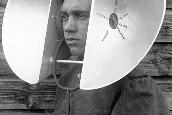
The Dutch personal parabola, 1930s. This personal sound locator consists of two parabolic sections, presumably made from aluminium for lightness. They are mounted a fixed distance apart, but the size of the human head varies somewhat. To accommodate this, it appears that the instrument is fitted with inflatable ear-pads. According to a report dated 1935, this device was put into at least limited production.

Dutch personal horns: 1930s. This design no doubt had more gain, thanks to its greater area. It swiveled on the post behind the operator. On the right, a later version of the design on the left. Note the extra cross-bracing added at the top of the horns. There are two counter-weights sticking out towards the rear. Rubber rings cushioned the operator’s ears.

A Czech locator, 1920s. Scoop-shaped reflectors direct the sound into large-diameter tubes. Manufactured by Goerz. When tested at the Dutch military research station at Waalsdorp it was found it “contained fundamental deficiencies”.

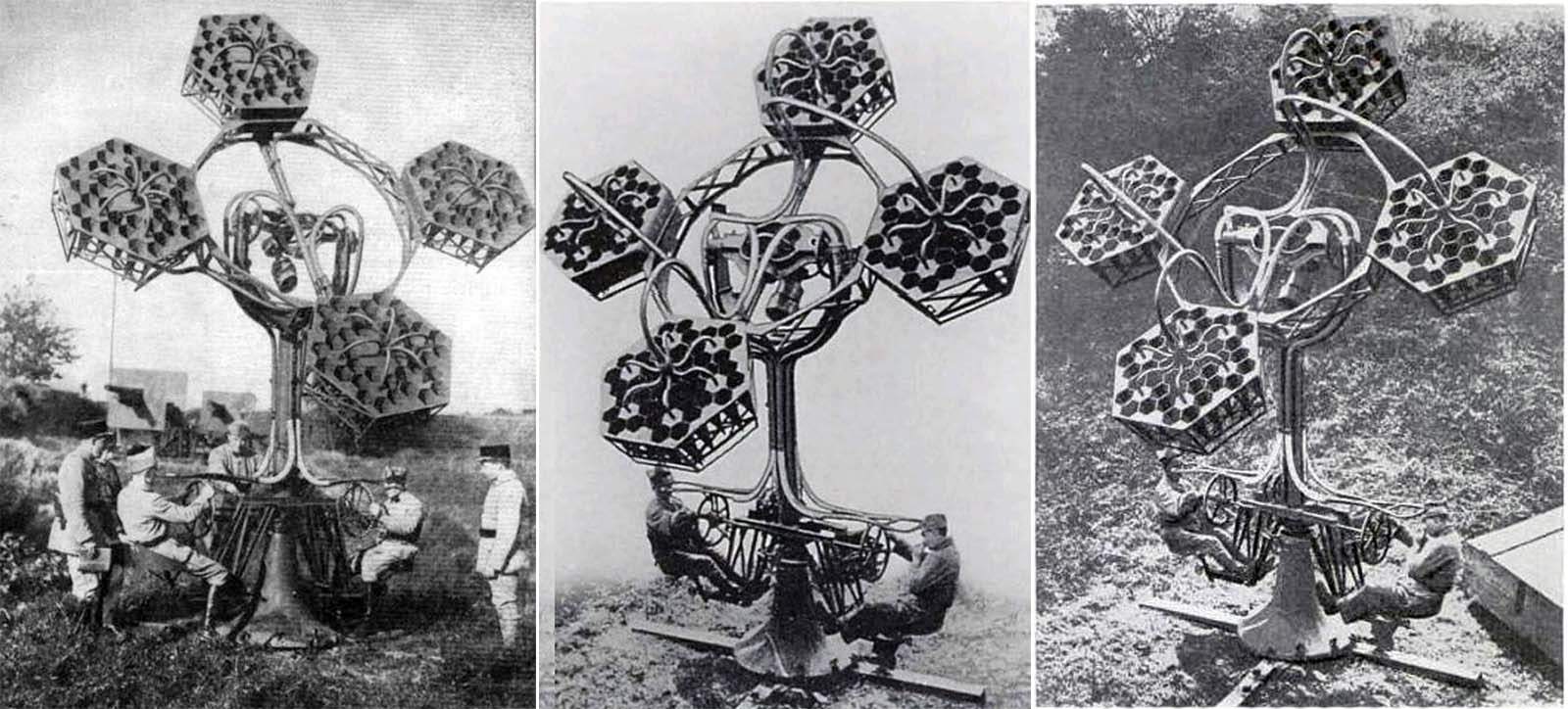
Perrin acoustic locator on trial in France. 1930s. This machine was designed by French Nobel prizewinner Jean-Baptiste Perrin. Each of the four assemblies carries 36 small hexagonal horns, arranged in six groups of six. Presumably, this arrangement was intended to increase the gain or directionality of the instrument.

German acoustic locator in use. This device was based on the researches of Erich von Hornbostel. With Max Wertheimer, he developed in 1915 a directional listening device that they referred to as the Wertbostel. This device seems to have had some success as they were still discussing license fees with manufacturers as late as 1934.

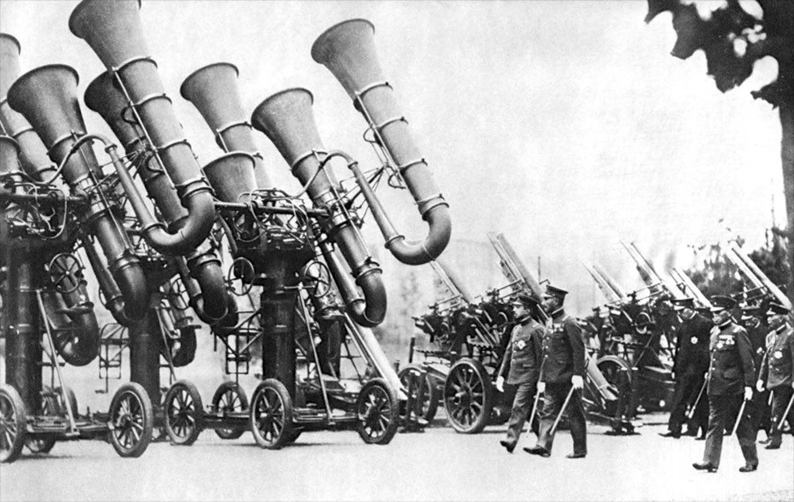
Three Japanese acoustic locators, colloquially known as “war tubas”, mounted on four-wheel carriages, being inspected by Emperor Hirohito.


